
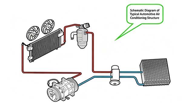
توصّل أنابيب تكييف الهواء المكوّنات الرئيسية الأربعة للنظام — الضاغط، والمكثّف، والمبخّر، وصمام التمدد — لتشكيل نظام مغلق يتم داخله تخزين سائل التبريد أو دورانه. عندما يكون نظام تكييف الهواء قيد التشغيل، يدور سائل التبريد بشكل مستمر، ويتبادل الحرارة مع البيئة الخارجية لتحقيق وظيفة التبريد. ولضمان نقل سائل التبريد للحرارة بسلاسة وكفاءة، يجب أن يكون مسار الأنابيب مصممًا جيدًا، بما يسهّل كلاً من التجميع والتفكيك، مع سهولة التصنيع وفعالية التكلفة.
أنابيب الألمنيوم، والخراطيم المطاطية، ووصلات الأنابيب
تُربط هذه المكوّنات الثلاثة معًا لتوصيل الأجزاء المختلفة لنظام تكييف الهواء. تُوصل أنابيب الألمنيوم والخراطيم المطاطية باستخدام عملية الكبس؛ ومع ذلك، قد توجد اختلافات طفيفة في أبعاد الكبس بين نماذج الأنابيب المختلفة وتلك المصنّعة من قبل شركات مختلفة. يمكن أن تتسبب اهتزازات المحرك في تلف شبكة الأنابيب؛ ويساعد استخدام الخراطيم المرنة في شبكة الأنابيب التي تصل منافذ السحب والتفريغ للضاغط على امتصاص هذه الاهتزازات، وتحسين إحكام النظام، وإطالة عمر خدمة شبكة الأنابيب. علاوة على ذلك، قد تُصنع بعض أقسام شبكة الأنابيب، مثل خط المكثّف–المبخّر، بالكامل من أنابيب الألمنيوم. ويرجع ذلك أساسًا إلى محدودية الحركة النسبية بين المكثّف والمبخّر.
إذا ترك التصميم خلوصًا صغيرًا بين شبكة الأنابيب والمكوّنات المحيطة، أو إذا كانت متلامسة بالفعل بشكل قريب، يمكن النظر في استخدام أكمام مقاومة للتآكل مثل أنابيب الانكماش الحراري، أو الأنابيب المموجة، أو الرغوة. وإذا كان الخلوص بين أنابيب تكييف الهواء ومجمع عادم المحرك صغيرًا، فيجب اتخاذ إجراءات للعزل الحراري، مثل تغليف الخرطوم بكمّ عازل للحرارة مصنوع من رقائق الألمنيوم.
وصلات الأنابيب والحلقات الدائرية O-rings
تُستخدم وصلات الأنابيب لتوصيل أنابيب تكييف الهواء والمكوّنات المختلفة للنظام. وتشمل الأنواع المستخدمة حاليًا بشكل شائع: وصلات المشابك، والوصلات الملولبة، والوصلات سريعة التوصيل.
تتمثل وظيفة الحلقة الدائرية O-ring في إحكام وصلة الأنبوب. والمادة المستخدمة حاليًا للحلقات الدائرية O-rings هي HNBR.
مشبك الأنبوب
الغرض من مشابك الأنابيب هو تثبيت شبكة أنابيب تكييف الهواء بهيكل المركبة، ومنع الحركة النسبية بينهما، وبالتالي تجنب التداخل بين الأنابيب المهتزة والمكوّنات المحيطة، وكذلك منع تسرب سائل التبريد عند الوصلات.
بالإضافة إلى مشابك الأنابيب المعدنية، يمكن أيضًا استخدام مشابك الأنابيب البلاستيكية لتثبيت شبكة أنابيب تكييف الهواء. في الوقت الحالي، يوجد نطاق محدود من مشابك الأنابيب البلاستيكية المستخدمة في نظام تكييف الهواء لمنصة S؛ ومع ذلك، يمكن النظر في تطوير مشابك أنابيب بلاستيكية مستقبلًا مع مراعاة عوامل مثل المشاريع الجديدة وخفض التكلفة.
عند استخدام مشابك الأنابيب، يجب أيضًا تركيب بطانات مطاطية داخل المشابك لتخفيف الاهتزازات ومنع الضوضاء الناتجة عن التلامس المباشر بين أنبوب الألمنيوم والمشبك.
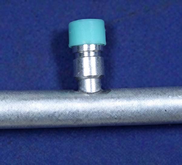
منفذ تعبئة الضغط المنخفض
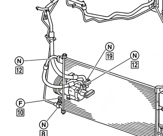
تتمثل وظيفتها في شحن واستعادة سائل التبريد، بالإضافة إلى فحص ضغط النظام. عادةً ما يُركّب منفذ الشحن عالي الضغط على خط المكثّف–المبخّر، على الرغم من أن بعضها يُركّب على خط الضاغط–المكثّف. أما منفذ الشحن منخفض الضغط فيُركّب على خط المبخّر–الضاغط. يظهر شكل منافذ الشحن في الشكل التوضيحي. علاوة على ذلك، يجب تزويد منافذ الشحن بأغطية غبار. تكون هذه الأغطية عادةً خضراء اللون (على الرغم من وجود متطلب حالي لتغييرها إلى اللون الأزرق) ومصنوعة من PP.
مفاتيح/حساسات الضغط
مفتاح/حساس الضغط هو مكوّن لكشف الضغط يراقب الضغط الداخلي للنظام في الوقت الفعلي، ويحمي نظام تكييف الهواء عن طريق إيقاف الضاغط في حال وجود ضغط غير طبيعي، مما يحافظ على سلامة النظام. كما يُستخدم للتحكم في سرعة مروحة التبريد. يظهر مفتاح/حساس الضغط في الشكل التوضيحي.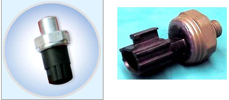
كاتم الصوت
عندما تتسبب عيوب التصميم في نظام تكييف الهواء بحدوث ضوضاء في شبكة الأنابيب، يمكن تركيب كواتم صوت عند مصدر الضوضاء المحدد للتخلص منها. تُركّب كواتم الصوت عادةً على أنابيب الضغط المنخفض، بالقرب من مدخل سحب الضاغط عادةً. يجب تحديد موقع التركيب الدقيق من خلال الاختبارات. ويُفضّل منع حدوث الضوضاء من البداية عبر تحسين تصميم النظام.
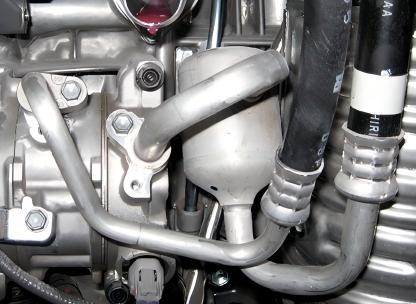
فاصل الغاز والسائل
عندما يكون حجم نظام تكييف الهواء غير مناسب، مما يؤدي إلى وجود سائل تبريد في أنابيب الضغط المنخفض، فقد يتسبب ذلك في حدوث المطرقة السائلة داخل الضاغط؛ ويمكن أن يحمي استخدام فاصل الغاز والسائل الضاغط من التلف. يُركّب هذا المكوّن على خط المبخّر–الضاغط. ونادرًا ما يوجد هذا المكوّن في المركبات الحديثة، إذ يمكن تجنب المشكلة من خلال تحديد حجم النظام بشكل صحيح.
في حالة أنابيب المشابك الملحومة، يُلحَم المشبك بالأنبوب بعد ثني الأنبوب. تتم معالجة رأس المشبك آليًا، مما يضمن تحكمًا دقيقًا نسبيًا في الأبعاد. أما في أنابيب المشابك المشكلة بالضغط، فيُركّب المشبك (الذي لا يحتوي على هيكل رأس) أولاً على الأنبوب، ثم يُشكّل الأنبوب بالضغط لتثبيته بإحكام على المشبك. يجب أن يفي العزم المطبق على هذا المشبك بالمتطلبات المحددة. (حاليًا، متطلب العزم للمشابك على أنابيب ¢12 و¢16 هو 11 N·m، بينما للأنابيب ¢10 هو 6 N·m.) ثم تُشكّل نهايات الأنابيب باستخدام آلة تشكيل نهايات الأنابيب، أو آلة التخديد، أو معدات مماثلة. والمرحلة النهائية هي عملية ثني الأنابيب.
نظرًا لأن الأنابيب تخضع لقيود القوالب والآلات أثناء التصنيع، يجب مراعاة النقاط التالية عند إعداد بيانات الأنابيب.
① أنصاف أقطار الثني لأنابيب الألمنيوم هي R15/20 (¢10)، وR20 (¢12)، وR25 (¢16). وتبلغ هذه القيم عمومًا 1.5 مرة من القطر الخارجي للأنبوب.
② يجب أن يكون طول أقصر جزء مستقيم من الخط المركزي لخط الأنابيب أكبر من 20 مم. ويقتصر هذا الطول بشكل أساسي على عاملين:
1) قيود السماكة لقوالب ثني الأنابيب.
2) إذا كان الأنبوب قصيرًا جدًا، فقد يلامس آلة ثني الأنابيب أثناء الثني، مما يؤدي إلى حدوث تلف أو تشوه.
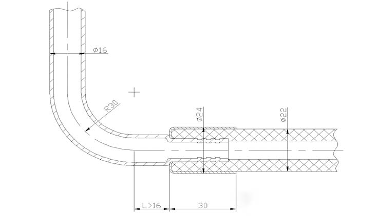
③ يجب أن تكون المسافة الدنيا L بين نقطة القطع والأنبوب المكبوس على طول الخط المركزي لأنبوب الألمنيوم أكبر من 16 مم؛ ويجب ألا توجد مكوّنات أخرى في اتجاه الأنبوب المكبوس يمكن أن تتداخل مع عملية الكبس.
④ يبلغ طول أقصر جزء مستقيم عند نهاية الطرف المتسع 20 مم. وتختلف هذه القيمة قليلًا حسب قطر الأنبوب. كما يجب تحديد القيم المذكورة أعلاه بالرجوع إلى مسار شبكة الأنابيب.
المخطط الذي يوضح العلاقة بين معلمات ثني الأنابيب هو كما يلي:
تُصنّف مفاتيح الضغط إلى نوع ثلاثي المواضع أو ثنائي المواضع؛ ويُحلل مبدأ تشغيل مفتاح الضغط ثلاثي المواضع أدناه.
1) عندما يكون ضغط سائل التبريد ≤ 0.12 ± 0.02 MPa، وبما أن القوة المرنة للحجاب الحاجز والنابض القرصي والنابض العلوي تتجاوز ضغط سائل التبريد، تفتح نقاط التلامس عالية ومنخفضة الضغط (OFF)، مما يؤدي إلى توقف الضاغط، وبالتالي توفير حماية من الضغط المنخفض.
2) عندما يصل ضغط سائل التبريد إلى 0.24 MPa أو أكثر — وهو ضغط أعلى من قوة نابض المفتاح — ينحرف النابض، مما يؤدي إلى إغلاق نقاط التلامس عالية ومنخفضة الضغط (ON)، ويعمل الضاغط بشكل طبيعي.
3) عندما يصل ضغط سائل التبريد إلى 3.2 MPa أو أكثر، فإنه يتجاوز القوة المرنة للحجاب الحاجز والنابض القرصي؛ فيعكس النابض القرصي اتجاهه لفصل نقاط التلامس عالية ومنخفضة الضغط، مما يؤدي إلى توقف الضاغط وبالتالي توفير حماية من الضغط العالي.
4) مفتاح الضغط المتوسط. عندما يتجاوز ضغط سائل التبريد 1.6 ميغاباسكال، يتغلب الضغط على قوة زنبرك الحجاب الحاجز، مما يؤدي إلى عكس اتجاه حركة الحجاب الحاجز ودفع العمود إلى الأعلى، وبالتالي إغلاق نقطة تلامس تغيير السرعة لمروحة المكثف (أو مروحة المبرد). تعمل المروحة بعد ذلك بسرعة عالية، مما يوفر حماية من الضغط المتوسط. عندما ينخفض الضغط إلى 1.25 ميغاباسكال، يعود الحجاب الحاجز إلى موضعه الأصلي، ويتحرك العمود إلى الأسفل، وتفتح نقاط التلامس، وتعمل مروحة المكثف بسرعة منخفضة.
تخطيط مجاري أنابيب تكييف الهواء
تُستخدم أنابيب تكييف الهواء لنقل سائل التبريد داخل نظام تكييف الهواء؛ لذلك، يجب أن يتضمن التخطيط المصمم جيدًا لأنابيب تكييف الهواء النقاط التالية:
① تتميز الأنابيب بموثوقية عالية، مما يضمن عدم وجود تسربات لسائل التبريد.
② لا تؤثر على أداء التبريد لنظام تكييف الهواء—مع الحفاظ على ارتفاع درجة حرارة سائل التبريد، وانخفاض الضغط، ومعدل عودة زيت الضاغط ضمن الحدود المناسبة.
③ تلبي متطلبات NVH دون إدخال اهتزازات أو ضوضاء إضافية.
④ تلبي متطلبات التجميع النهائي والصيانة بعد البيع.
⑤ تحسين التكلفة.
⑥ يجب أن يكون المظهر العام جماليًا قدر الإمكان.
فيما يلي، سنناقش كلًا من هذه الخصائص بالتفصيل من منظور تخطيط الأنابيب.
موثوقية خطوط الأنابيب
استنادًا إلى أنماط الأعطال التي لوحظت في أنابيب الطرازات السابقة، حددنا بشكل عام عدة أسباب رئيسية لتلف الأنابيب:
① تتعرض الأنابيب المصنوعة من الألمنيوم أو الخراطيم المطاطية للتآكل بسبب المكونات المحيطة بها
② تنكسر الأنابيب المصنوعة من الألمنيوم أو الخراطيم المطاطية نتيجة اهتزازات المحرك
③ حدوث تلف بسبب الحرارة الزائدة عند وصلة الخرطوم
1) لمنع تآكل الأنابيب بسبب المكونات المحيطة بها، يجب توفير خلوص مناسب عند توجيه الأنابيب. نظرًا لأن المركبة الآلية عبارة عن آلة متحركة أثناء الاستخدام، يجب أن يأخذ هذا الخلوص في الحسبان الخلوص الساكن والديناميكي معًا. يشير الخلوص الساكن إلى الفجوة بين جسمين مع وجود اهتزازات ضئيلة (حيث إن جميع المكونات تقريبًا تهتز أثناء حركة المركبة)، مثل المسافة بين المصابيح الأمامية وأنابيب المكثف–المبخر، أو بين هيكل المركبة وأنابيب المكثف–المبخر؛ ويوصى بالحفاظ على هذا الخلوص عند 15 مم أو أكثر. إذا كان الخلوص صغيرًا جدًا أو معدومًا ولا يمكن تجنب مسار التوجيه، فيجب تغليف الأنابيب القريبة من بعضها بالرغوة أو الأنابيب المنكمشة حراريًا أو الأنابيب المموجة.
نظرًا لأن المحرك يهتز أثناء التشغيل، يجب أخذ الخلوصات الديناميكية في الاعتبار للأنبوبين المتصلين بالضاغط. على سبيل المثال، الخلوص بين خراطيم مدخل ومخرج الضاغط والمروحة وسير القيادة. إذا كان الخلوص صغيرًا جدًا، فقد يتسبب الاهتزاز الأمامي للمحرك في تداخل خراطيم تكييف الهواء مع المكونات الأخرى؛ وبالتالي، فإن متطلبات الخلوص الديناميكي أكثر صرامة من متطلبات الخلوص الساكن، ويتم تحديدها عمومًا بمقدار 20 مم أو أكثر. وبما أن المحرك يميل إلى الاهتزاز بشكل أساسي في الاتجاه الطولي للمركبة، فمن الأفضل توجيه الخراطيم المتصلة بالضاغط بشكل عمودي على المستوى XZ.
عند توجيه الأنابيب، يجب إبقاؤها بعيدة قدر الإمكان عن المكونات ذات درجات الحرارة العالية (أنابيب العادم) في الحجرة الأمامية، مع الحفاظ على مسافة لا تقل عن 100 مم. إذا كان من المستحيل فعليًا تلبية هذا المتطلب، فيجب أن تكون المسافة الدنيا أكبر من 40 مم، ويجب تغليف السطح بورق ألمنيوم عازل للحرارة.
اهتزاز وضوضاء خطوط الأنابيب
ينتج اهتزاز مجاري أنابيب تكييف الهواء بشكل رئيسي عن العوامل التالية:
طرق تثبيت الأنابيب والمكونات المرتبطة بها؛
اختيار أنواع الخراطيم للأنابيب؛
الضوضاء الناتجة عن تخطيط الأنابيب.
ستتم مناقشة هذه الخصائص الثلاث بالتتابع أدناه:
يجب تزويد دعامات الأنابيب بحشيات مطاطية لمنع التوصيلات الصلبة. وإذا تم استخدام مشابك أنابيب بلاستيكية، فمن المستحسن أيضًا استخدام الحشيات.
يمكن اختيار خراطيم مطاطية بالكامل للأنابيب منخفضة الضغط؛ ونظرًا لمرونتها النسبية، فإنها تستطيع امتصاص الاهتزازات بفعالية وتقليل الضوضاء في الأنابيب.
لتقليل الضوضاء الناتجة عن أنابيب تكييف الهواء، يجب تمديد الأنابيب بأقصر مسار وأكثره استقامة ممكنة؛ كما يقلل ذلك من كمية سائل التبريد المطلوبة.
بالإضافة إلى ذلك، يمكن تركيب كاتم صوت على الأنابيب؛ حيث يعمل على تخفيف وامتصاص نبضات الضغط المتولدة داخل النظام. ويُعد موضع تركيب كاتم الصوت أمرًا بالغ الأهمية ويتطلب عدة تجارب لتحديد الموقع الصحيح. يجب تركيب كاتم الصوت بالقرب من طرف الضاغط قدر الإمكان، ويجب أن يكون هناك ما لا يقل عن 25 مم من الأنابيب المستقيمة على جانبي كاتم الصوت.


 Whatsapp :
  هاتف :
  بريد الالكتروني :